Vacuum Conveyor and Vibro Sifter System: How to Design a Dust-Free Powder Line
A vacuum conveyor and vibro sifter system combines enclosed powder transfer with screening to remove oversized particles and reduce manual handling. It can connect feeding points with mixers, storage hoppers, or packaging equipment, helping control dust during material transfer.
Designing a reliable system requires matching conveying capacity with screening performance, coordinating equipment connections, and controlling dust at feeding and discharge points. This guide explains the key considerations for a powder handling line that meets your material characteristics, production requirements, and available installation space.
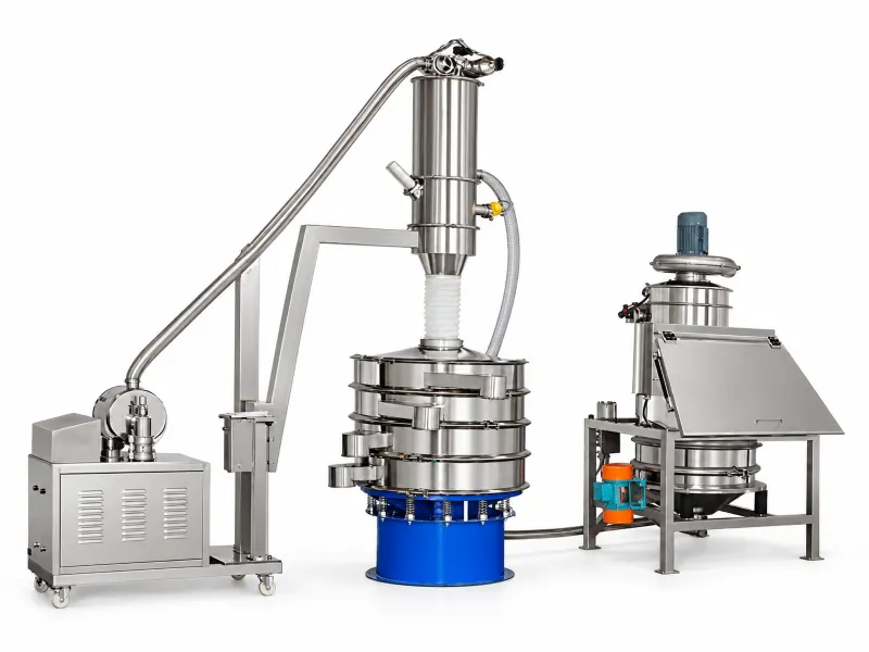
How Does a Vacuum Conveyor and Vibro Sifter System Work?
The conveyor transfers powder between process points, while the sifter separates particles according to the selected mesh opening. Their operation must be coordinated so material transfer supports stable screening.
Vacuum Conveyor: Enclosed Powder Transfer
Il vacuum conveyor uses negative pressure to draw powder through enclosed piping into a receiving hopper. A filter separates the powder from the conveying air, and a discharge valve releases the collected material. Automatic conveying and discharge cycles reduce manual feeding and help limit dust release.
Vibro Sifter: Controlled Particle Separation
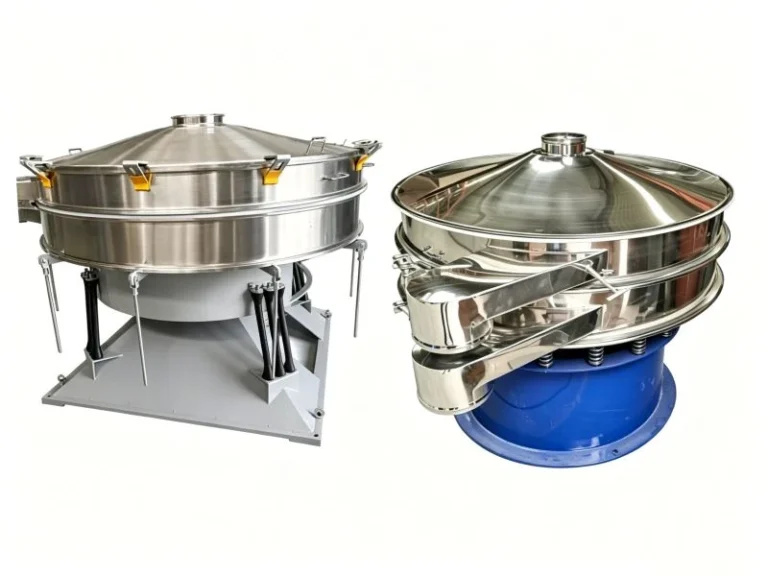
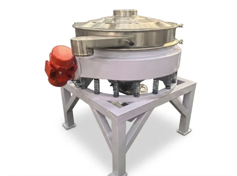
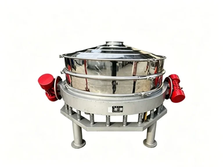
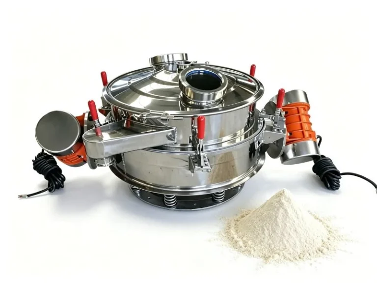
Il vibro sifter uses vibration to move material across a screen mesh. Smaller particles pass through the openings, while oversized particles are retained and directed to a separate outlet. Interchangeable screens allow the machine to meet different screening requirements.
Combined Operation: Coordinated Conveying and Screening
The equipment is connected according to the production process, with conveying cycles and feed rates coordinated to support stable screening. Where needed, a buffer hopper or controlled feeder helps manage intermittent discharge.
How to Connect a Vacuum Conveyor and Vibro Sifter in a Powder Line
A vacuum conveyor and vibro sifter can be connected directly or through a buffer hopper with a controlled feeder. The suitable arrangement depends on powder flowability, discharge volume, available space, and the feed rate required for stable screening. The following configurations apply when the vacuum conveyor feeds the sifter.
Direct Connection: Compact Transfer to the Sifter
The vacuum receiver’s discharge outlet connects to the vibro sifter inlet through a suitable flexible connection. Collected powder is released into the sifter during each discharge cycle.
This arrangement suits free-flowing powders when the sifter can handle the incoming discharge without material buildup. It requires fewer components and offers a compact layout. Connection dimensions, installation height, and flexibility should be checked to accommodate sifter movement and allow maintenance access.
Buffer Hopper Connection: More Consistent Feeding
A buffer hopper receives powder discharged from the vacuum conveyor. A screw feeder or another suitable feeding device then supplies the vibro sifter at a controlled rate.
This arrangement is useful when intermittent discharge creates feed surges or the screening process requires more consistent loading. The hopper provides temporary storage, while the feeder regulates delivery to help prevent screen overloading.
Hopper geometry and feeder selection should match the powder’s flow characteristics. Powders prone to bridging or hard lumps may require additional flow assistance or separate pretreatment.
For broader guidance on installation points and connections to downstream equipment, see our guide to integrating an inline powder sieving system.
How Do You Match Conveying Capacity with Sifting Performance?
Matching conveying and screening capacity requires more than comparing rated output. A vacuum conveyor and vibro sifter system must deliver powder at a rate the screen can process effectively. Powder characteristics, mesh opening, conveying conditions, and discharge cycles all influence performance.
The goal is to maintain a consistent material layer without overloading or underfeeding the screen.
Match Capacity to the Actual Powder and Process
Confirm the powder’s bulk density, flowability, moisture content, and particle size, together with the required screening result.
Conveying capacity should be checked against the actual pipe length, vertical lift, and operating cycle. Sifting capacity should be verified using the intended powder and mesh rather than the machine’s maximum rated output.
Maintain an Even Material Layer on the Screen
Excessive feeding can create a thick material layer, preventing smaller particles from reaching the mesh before moving toward the oversize outlet. Insufficient feeding may leave screening capacity underused.
Adjust the feed rate to maintain an even layer, with the suitable thickness established through material trials and screening results.
Coordinate Discharge Cycles with PLC Controls
PLC controls can coordinate conveying, discharge, and sifter operation through a defined operating sequence. Level signals can pause upstream feeding when material accumulates or downstream equipment is full.
For systems with intermittent vacuum discharge, adjust the conveying cycle and controlled feeding rate to prevent sudden loads from overwhelming the screen.
Adjust Parameters and Monitor Performance
Set suction and discharge times according to material behavior and production demand. Adjust feeder output and, where supported, sifter settings within the equipment manufacturer’s recommended range.
Optional level sensors, weighing devices, and filter differential-pressure monitoring can help track operating conditions. Timed conveying cycles alone do not guarantee accurate dosing; applications requiring precise quantities need suitable weighing or metering equipment.
Confirm screening performance through throughput checks and samples from the product and oversize outlets.

How Can You Control Dust at Every Transfer Point?
Dust control requires attention to feeding, equipment connections, screening, and discharge. Enclosed conveying, suitable seals, and local dust extraction help reduce powder escape and material loss. The layout can be customized to suit available space, production capacity, and powder characteristics.
Capture Dust at Bag Opening and Feeding
Opening and emptying powder bags can release dust even when the downstream conveying system is enclosed. A dust-free bag dump station with suitable local extraction helps capture airborne powder at the feeding point. Its collection arrangement should match the bag-handling method and feeding rate.
Seal Connections Without Restricting Sifter Movement
Fit suitable seals at covers, inlet connections, and discharge outlets. Flexible connections between the vibrating sifter and stationary equipment should accommodate movement without excessive tension or material accumulation.
Check clamps, gaskets, and hoses regularly, as worn or loose connections can allow powder to escape.
Manage Filtration, Venting and Reject Discharge
Select conveying filters for the powder being handled and maintain effective filter cleaning. Receiving containers need appropriate filtered venting or extraction to manage displaced air during filling.
Both screened powder and oversized material should discharge into enclosed receiving arrangements to limit dust release.
Allow Easy Cleaning and Product Changeover
Provide access for cleaning screens, filters, and connection points without unnecessary powder spillage. Remove retained powder before product changeovers.
For chemical and pharmaceutical powders, select contact materials, seals, and containment measures according to the specific process requirements.
These measures support cleaner operation, but enclosed equipment alone does not guarantee zero dust emissions. Performance depends on the complete system design, operating conditions, and maintenance.
For a practical example, see our flour screening and vacuum conveying case study, which combines a dust-free feeding station, an inline screen, and enclosed vacuum transfer to reduce manual handling.